Dies
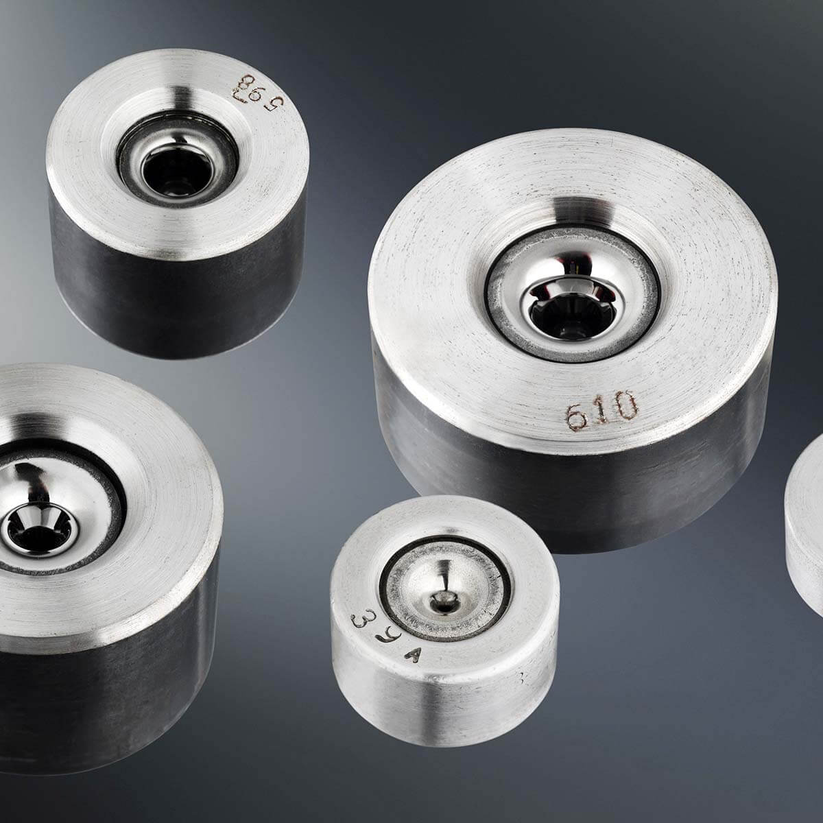
Sintered carbide drawing dies for towing steel wires of circular cross-section.
Technical specification
 | A – Core B – Input part C – Drawing part D – Calibrating part E – Output part F – Socket ⌀d1 – Diameter of calibrating cylinder ⌀d2 – Diameter of core ⌀d3 – Diameter of socket h2 – Height of core h3 – Height of socket l2 – Length of drawing cone core l3 – Length of calibrating cone of core l4 – Length of output cone of core l5 – Length of input cylinder of socket 2α – Angle of drawing cone of core 2β – Angle of input cone of core 2γ – Angle of output cone of core 2δ – Angle of output cone of socket |
Types and sizes of dies
| Type | Nominal diameter d1 (mm) | Simensions of the core | Dimensions of the sleeve | |||
|---|---|---|---|---|---|---|
| ⌀ d2 ≈ (mm) | h2 ≈ (mm) | ⌀ d3 ±0,2 (mm) | h3 ±0,5 (mm) | l5 ≈ (mm) | ||
| M1U | 0,15 – 2,20 | 9 | 6 | 28 | 14 | 1,5 |
| M1N | 0,20 – 2,50 | 10 | 8 | 28 | 14 | 1,5 |
| M1S | 0,35 – 2,20 | 16 | 13 | 28 | 16 | 1 |
| M2 | 1,20 – 2,20 | 14 | 12 | 43 | 22 | 3 |
| M3 | 3,00 – 12,00 | 30 | 24 | 70 | 34 | 4 |
| 75 | 40 | |||||
| M4 | 12,0 – 22,00 | 35 | 24 | 70 | 34 | 4 |
| 75 | 40 | |||||
| S1 | 0,60 – 2,20 | 12 | 10 | 28 | 20 | 2 |
| S2 | 0,40 – 4,00 | 16 | 13 | 43 | 25 | 4 |
| S3 | 1,80 – 6,50 | 20 | 17 | 43 | 32 | 5 |
| S4 | 2,50 – 10,00 | 25 | 20 | 53 | 35 | 4 |
Average Tolerances of d1
| Nominal diameter of die d1 | Tolerances ⌀ d1 |
|---|---|
| 0,15 – 1,00 | -0,005 |
| 1,01 – 4,00 | -0,01 |
| 4,01 – 20,00 | -0,02 |
Roundness deviation sectional calibration cylinders must not exceed the range limit deviations in diameter d1. By mutual agreement with the customer can deliver dies in other tolerances d1, than indicated in the table limit deviations.
The angles of the input and output cone
| Type | 2β ±5° | 2γ ±5° | 2δ ±5° |
|---|---|---|---|
| M1U | – | 60 | 60 |
| M1N | – | 60 | |
| M1S | – | 60 | |
| M2 | 60 | 60 | |
| M3 | 60 | 60 | |
| M4 | 60 | 60 | |
| S1 | – | 60 | |
| S2 | 60 | 60 | |
| S3 | 60 | 60 | |
| S4 | 60 | 60 |
For dies M1 and S1 is the angle 2β replaced rádius app. 4–6 mm. All crossing points between the individual parts are core hole smoothly rounded. Size towing cone core die 2α and the length of the calibration cylinder l3 depends on the way of wire drawing, and the material removal.
Types of dies for wire drawing with strength up to 1100 MPa for dry and wet
Sizes of towing cone and the length of the core
| Type | Nominal diameter d1 (mm) | 2α ±1° | l2≈ (mm) | l3≈ (mm) | l4≈ (mm) | Drawing method |
|---|---|---|---|---|---|---|
| M1U | 0,20 – 0,50 0,51 – 1,00 1,02 – 2,20 | 12 | 1,6 | 1 d1 0,8 d1 0,5 d1 | 1,5 | wet |
| M1N | 0,20 – 1,10 1,11 – 1,60 1,61 – 2,50 | 14 16 16 | 2 | 1 d1 0,7 d1 0,5 d1 | 2 | |
| M3 | 4,50 – 5,00 5,01 – 7,00 7,01 – 12,00 | 16 20 20 | 10 | 0,5 d1 0,4 d1 0,3 d1 | 4 | dry |
| M4 | 12,00 – 20,00 | 20 | 10 | 0,3 d1 | 4 | |
| S2 | 0,60 – 1,00 1,00 – 2,50 2,50 – 3,00 3,01 – 4,00 | 14 14 14 16 | 5,5 | 0,8 d1 0,5 d1 0,4 d1 0,4 d1 | 3 | |
| S3 | 3,00 – 4,00 4,00 – 5,00 5,01 – 6,50 | 16 16 20 | 6,5 | 0,4 d1 0,3 d1 0,3 d1 | 4 | |
| S4 | 2,50 – 5,00 5,01 – 7,00 7,01 – 10,00 | 16 20 20 | 6,5 | 0,5 d1 0,4 d1 0,3 d1 | 4 |
The length of the calibration cylinder l3 is given the aforementioned times with an inner diameter d1 (tolerance ±0,1 d1). When using smaller Uber for wire drawing dies are also used to tow wires with strength above 1100 MPa.
Types of dies for wire drawing with strength above 1100 MPa dry and wet
Sizes of towing cone and the length of the core
| Type | Nominal diameter d1 (mm) | 2α ±1° | l2 ≈ (mm) | l3 ≈ (mm) | l4 ≈ (mm) | Drawing method |
|---|---|---|---|---|---|---|
| M1U | 0,20 – 0,50 0,51 – 1,00 1,02 – 2,20 | 12 | 1,6 | 1 d1 0,8 d1 0,5 d1 | 1,5 | wet |
| M1S | 0,35 – 2,20 | 8 | 5,5 | 0,5 d1 | 3 | |
| M3 | 3,00 – 4,00 4,01 – 5,00 5,01 – 7,00 7,01 – 12,00 | 8 10 10 10 | 9 | 0,5 d1 0,4 d1 0,4 d1 0,3 d1 | 4 | dry |
| S2 | 0,40 – 0,99 1,00 – 2,50 2,51 – 4,00 | 8 | 5,5 | 0,75 d1 0,5 d1 0,4 d1 | 3 | |
| S3 | 2,00 – 2,50 2,51 – 4,00 4,01 – 5,00 5,01 – 6,50 | 8 8 10 10 | 6,5 | 0,5 d1 0,4 d1 0,3 d1 0,3 d1 | 4 | |
| S4 | 4,00 – 5,00 5,01 – 7,00 7,01 – 10,00 | 10 10 10 | 6,5 | 0,4 d1 0,4 d1 0,3 d1 | 4 |
The length of the calibration cylinder l3 is given the aforementioned times with an inner diameter d1 (tolerance ±0,1 d1). Drawing dies types M3, S2, S3 and S4 are indicated in the middle recess of the sleeve.
Types of dies for drawing steel cords
Sizes towing cone and the length of the core
| Type | Nominal diameter d1 (mm) | 2α ±1° | l2 ≈ (mm) | l3 ≈ (mm) ± 0,1 d1 | l4 ≈ (mm) |
|---|---|---|---|---|---|
| M1U | 0,15 – 2,00 | 8, 9, 10, 12 | 1,6 | 0,3 d1 | 1,5 |
Checking dies
All beams of circular cross section through output control:
- visual – magnifier at a magnification of 4–12× is checked quality of processing cores, which must be shiny, smooth, without grooves and holes,
- dimensional – girders inside diameters are measured and control pins such that at the lower tolerance control mandrel must pass a measured die and at the upper tolerance of the nominal diameter must not pass.
If you require a certificate (Declaration of Conformity), you have to apply for it.
Technical specification of the order
On Order must be marked:
- Subscriber
- type dies or diameter of the sleeve and the core
- nominal diameter d1(mm) and tolerance
- amount
- die geometry (towing cone size 2 alfa, the calibration length l3 or how to use a metal removal rates wires)
If parameters are required other than those listed above dies must be properly marked on the order form.
Packaging
Standard packaging is performed in cardboard boxes, or to normal Euro pallet.
More detailed information on the products can be provided by
- Ing. Lenka Víšková
- T +420 596 090 222
- +420 731 437 684
- E lenka.viskova@zdb.cz